KABK Fine Art BFA
3rd Year IST
F. Ó Súilleabháín
Introduction
Electro-Intaglio is the name I have given to this IST project. I’m following the handbook by Cedric Green “Green Prints”(2013) in which he gives some practical advice.
The idea is to etch copper plates using electrolysis. By immersing copper plates in a solution of copper sulphate and then passing a current between them, one plate gets eaten away and the other accretes copper. The copper is not simply transported from one plate to the other, rather, copper ions in the solution are attracted to the negative plate (the cathode) and sulphate ions are attracted to the positive plate. The sulphate ions react with the surface of the positive copper plate (the anode) in a similar way to the action of a mordant and this essentially dissolves away the exposed copper. By coating the anode plate (to be etched) with an intaglio etching ground and then drawing into it with an etching needle, a line etch may be obtained.
The advantage of using copper plates in a solution of copper sulphate is that no gases are liberated at the electrodes. Similarly, zinc plates could be used, immersed in a solution of zinc sulphate, to electro-etch zinc plates without the evolution of gases.
Materials
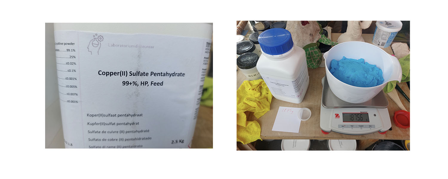
The Copper Sulphate
A molar solution of copper sulphate contains close to 250g/litre. This is also a saturated solution. It isn’t necessary to have a saturated solution for electrolysis so I mixed a 0.5 mol solution which is made up from 125g/litre. However, I wanted 15 litres so I dissolved 1.875kg in 15 litres distilled water. (If you use tap water there will likely be some dissolved salts, in some places the water is chlorinated so you might get unwanted chlorine gas produced during electrolysis).
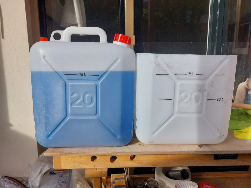
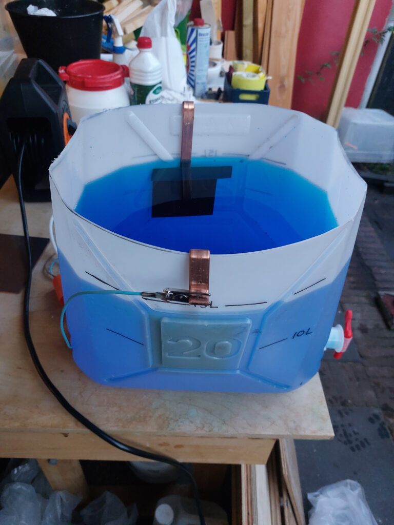
The Containers
I used plastic jerry cans, one for storage and one for the etching tank. The can for the etching tank had its top cut off with a jog saw to allow access.
Copper Plates
I used 3 sizes of copper plate for this study. The smallest size measured 9x12cm, the medium size were 10x15cm and the largest were 15x20cm.
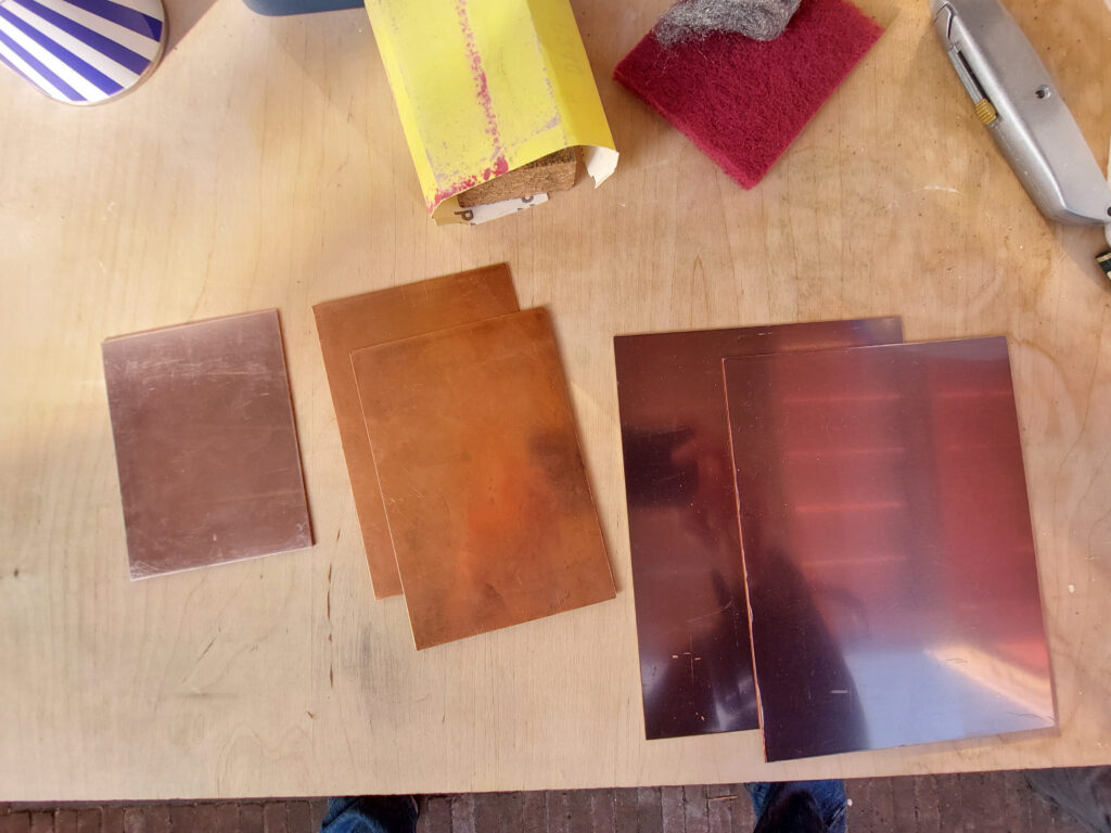
The plates are supplied with a thick self-adhesive protective film on the back and on the polished front they have a very thin self-adhesive plastic sheet. The back of the plate needs to be cleaned of adhesive residue and tarnish using wire wool and metal polish (Brasso). The front of these particular plates is supplied ready-polished so it just needs buffing with a cloth and metal polish to get a shiny mirror finish. The Brasso is quite oily so after polishing it was washed off with dish detergent. Next the plates are de-greased with whiting (calcium carbonate) and soy sauce (or vinegar), rubbed in with a paper towel. Finally the plates are washed again – when water forms a sheet on the surface with no beading they are sufficiently de-greased.
Calibration
Green (2013) decsribes a calibration process involving the use of two copper plates each of size 100 cm2.
I used two plates of 9x12cm (108 cm2 which is pretty close). Green suggests that you can measure the resistance of this configuration by varying the voltage across the plates, recording the current drawn and then using Ohm’s Law. That’s correct of course but he then provides an obviously empirically-determined rule involving what a table of what he terms “F-factors” and provides an equation to estimate the time for a light and a heavy bite for line etch. He then suggests these etching times are true for any arbitrary plate size which isn’t entirely true.
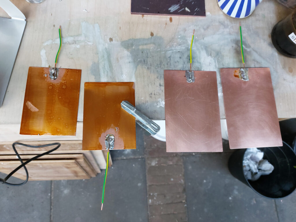
Following Green anyway, I used two 9x12cm plates cleaned and polished but bare-faced with no ground applied. I soldered copper wires to the backs to form the electrical contact. This required using a high-powered soldering iron (150W) because the small 25W irons used in electronics don’t cut it when soldering to a large piece of copper. The large copper plate just acts as a heatsink. Even a 150W iron struggled, ideally a brazing torch would have been better.
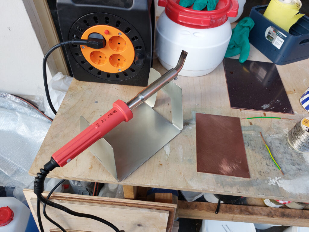
Even a 150W soldering iron is barely adequate
Green’s Calibration
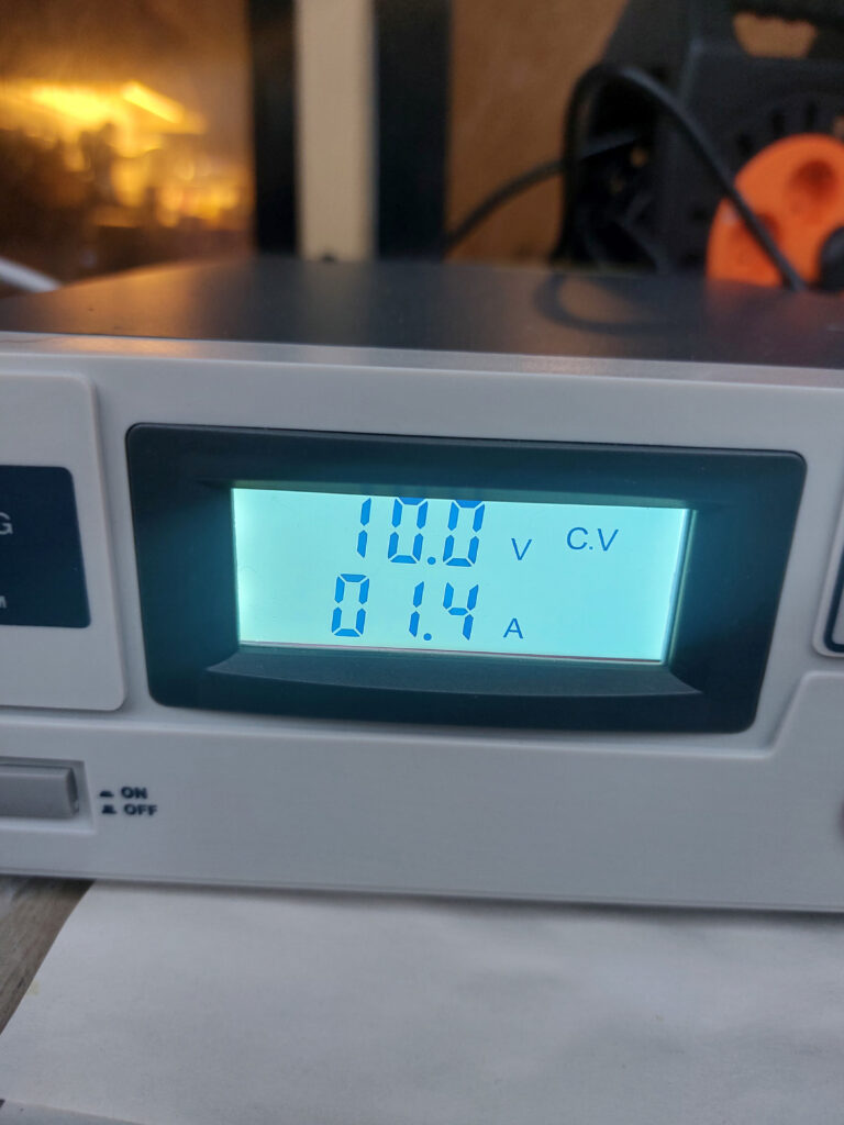
I used sets of plates in two sizes to perform Green’s calibration, varying the voltage and noting the current for each. The measured results and calculated values of resistance are shown in the tables below.
| Voltage (Volts) | Current (Amps) | Resistance (Ω) |
|---|---|---|
| 1.0 | 0.2 | 5.0 |
| 2.0 | 0.5 | 4.0 |
| 4.0 | 1.0 | 4.0 |
| 6.0 | 1.6 | 3.75 |
| 10.0 | 2.7 | 3.75 |
Table 1. Voltage and Current for 9x12cm bare plates
| Voltage (Volts) | Current (Amps) | Resistance (Ω) |
|---|---|---|
| 1.0 | 0.2 | 5.0 |
| 2.0 | 0.6 | 3.3 |
| 4.0 | 1.3 | 3.1 |
| 6.0 | 2.0 | 3.0 |
| 10.0 | 3.3 | 3.0 |
Table 2. Voltage and Current for 10x15cm bare plates
Green provides the following formula to obtain an estimate of the etching time, T, for a given voltage, V, and the resistance, R, measured with a plate of 100cm2.
![\[ T=\frac{F.R}{V} \]](https://kabkstudent.blog/wp-content/ql-cache/quicklatex.com-0d789fe33f1681ada0978fba097ae9e3_l3.png "Rendered by QuickLaTeX.com")
Strictly speaking just measuring the resistance in this way and just using a formula to obtain etch times for all plate sizes is not the way to do it. We should really use the measured resistance with a given plate size to calculate the resistivity of the electrolyte solution being used (recall this is 0.5 molar solution here). The resistivity is given by:
![\[ $\rho=\frac{R.A}{L} \]](https://kabkstudent.blog/wp-content/ql-cache/quicklatex.com-b1090bfbe50adf8cfe8829cc395563ee_l3.png "Rendered by QuickLaTeX.com")
where R is the measured resistance between two plates of area A separated by a distance L. In this way, we can calculate the theoretical resistance for any arbitrary plate size at any distance in a 0.5 molar solution. Calculating the resistivity of the solution using the measured resistances of each plate sizes I used above gave values of
![\[ $\rho=0.19\Omega m \]](https://kabkstudent.blog/wp-content/ql-cache/quicklatex.com-bf3107648716144c2e44960691a8721e_l3.png "Rendered by QuickLaTeX.com")
and
![\[ $\rho=0.21\Omega m \]](https://kabkstudent.blog/wp-content/ql-cache/quicklatex.com-3e772ef26ad07e5f857747f28a5b065b_l3.png "Rendered by QuickLaTeX.com")
So we might take an average between these two values. Returning to Green’s method, he provides values for copper of F=20 for a light bite and F= 60 to 80 for a deep etched line.
So taking my measured resistance from the 9x12cm plate of R=4Ω at 10Volts I obtain estimated etching times of 8 minutes for a light bitten line and 30 minutes for a deeply bitten line.
Calibration Step-Test Plates
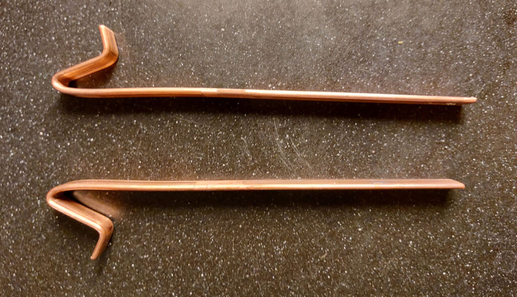
I decided to investigate the etching times in more detail. To do this I had to improve the way the electrical connection was made to the plates because the soldering was too much of mess. I fabricated two hangers from copper bar to hang on the side of the tank and these were attached simply by placing them in contact with the plates and using a self-adhesive film to hold them there.
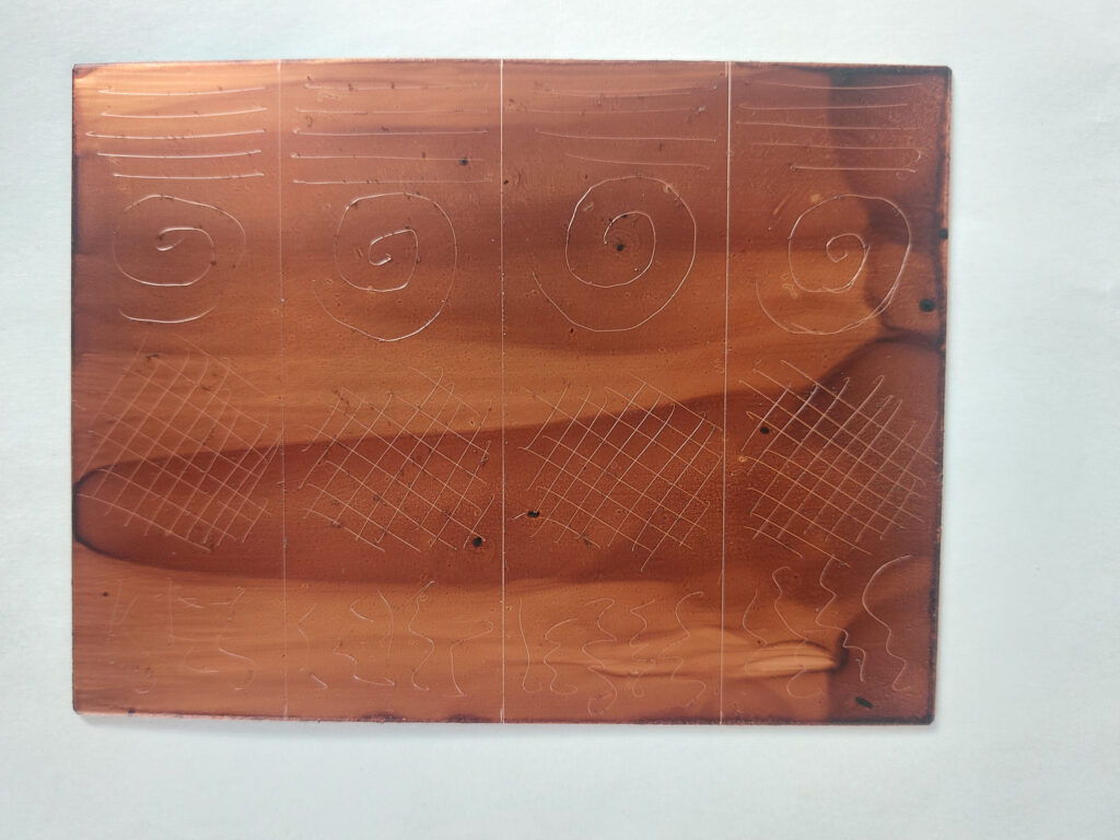
I cleaned up a 9x12cm plate and coated with traditional hard ground. I then drew an identical pattern in 4 vertical strips. Then by masking off each strip, apart from the first, I etched each strip at 10 volts for 15 minutes and then removed the tape from the next strip so I ended up with a plate with vertical sections etched for 15, 30, 45 and 60 minutes respectively.
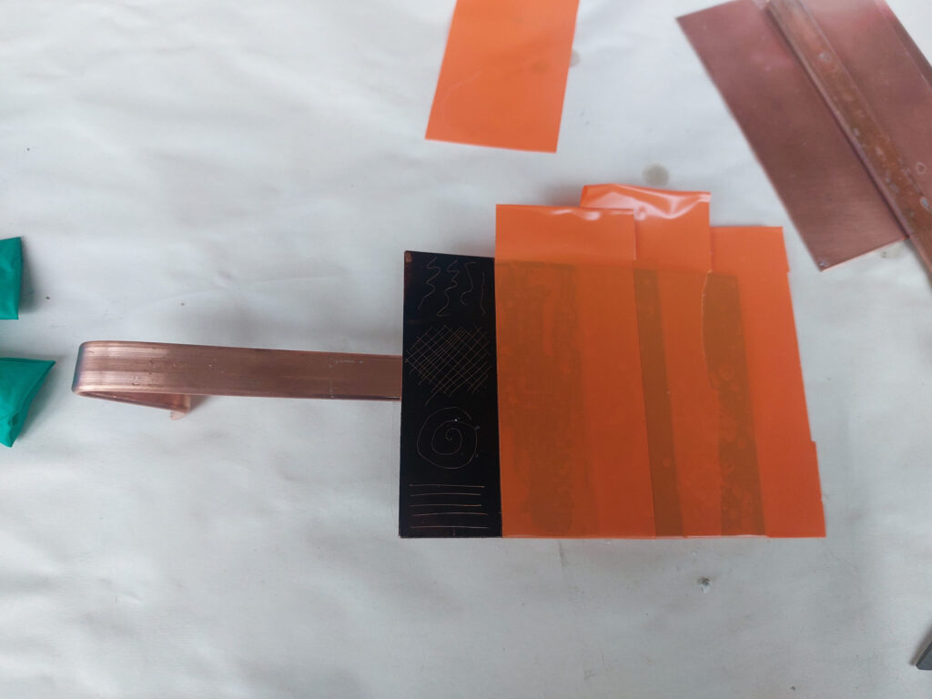
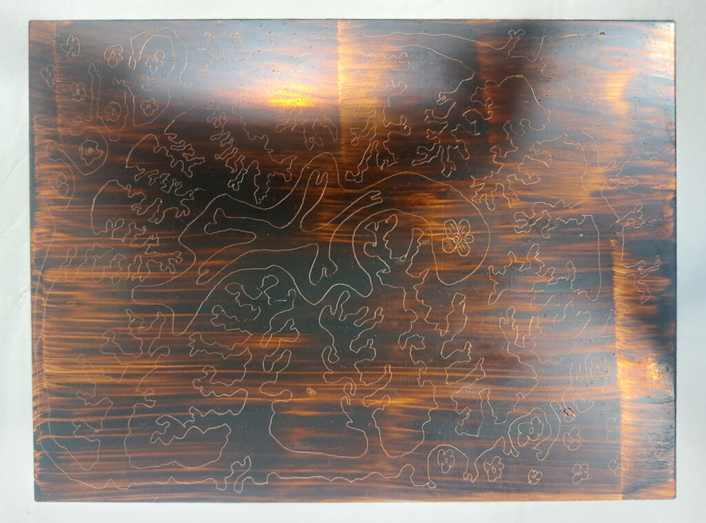
What I found was that the traditional ground was attacked by the electrolytic process and started to break down and created areas of open bite, particularly in the areas that had been etched the longest. See the etched plate below prior to cleaning off the ground. It is clearly visible where the ground has badly deteriorated.
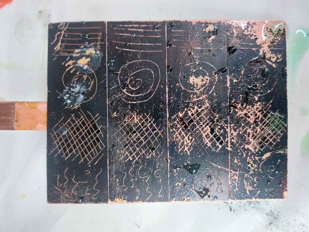
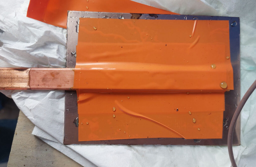
In addition to the breakdown of the ground, the adhesive on the plastic film started to fail so I had to replace it with a PVC tape (the bright orange one shown below, the same used to mask the front of the plate)
To try to improve matters, I prepared a second plate and this time used a Charbonnel liquid ground which is like a shellac varnish. It is much harder than the traditional ground of smoked bitumen of Judea and wax.
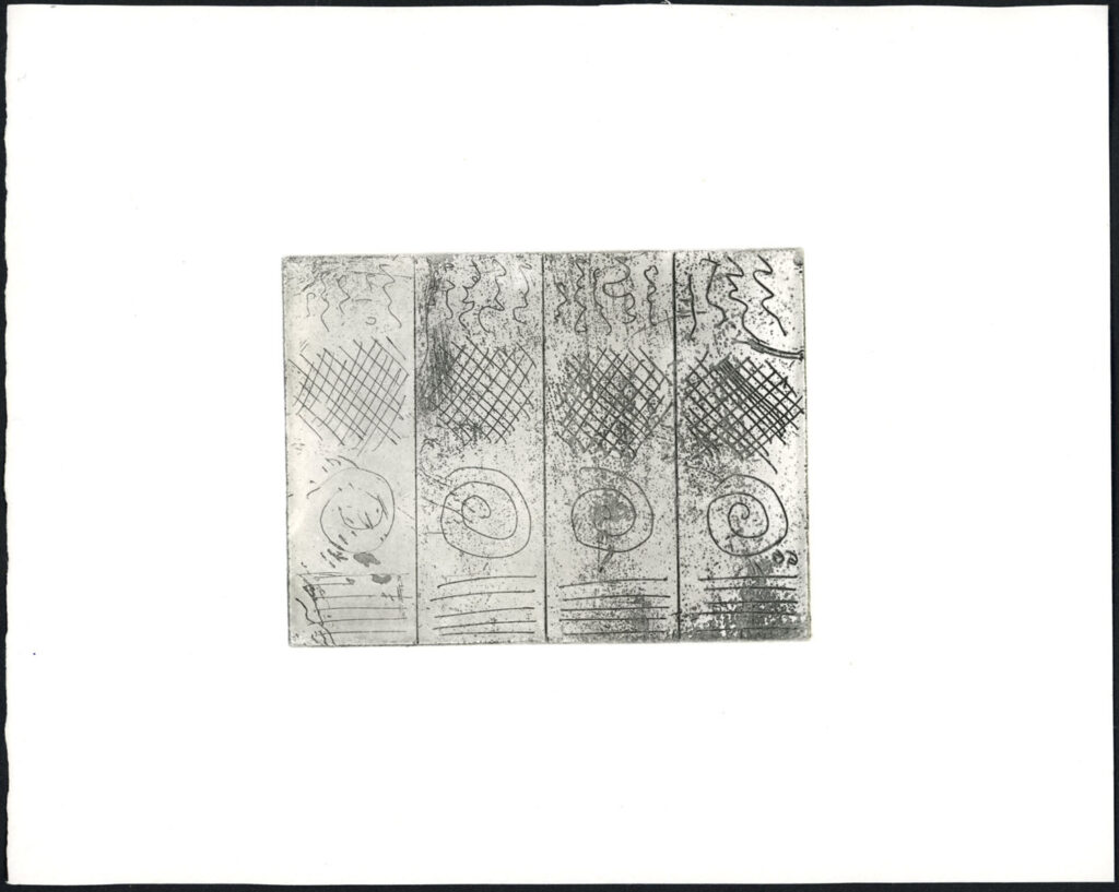
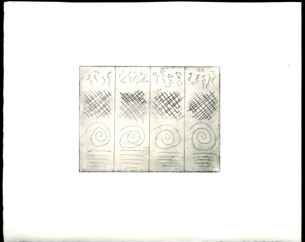
This plate was then etched at 5V to be a bit more conservative and for shorter times; The four different sections were etched for 5, 10, 15 and 20 minutes respectively. The etched plate (and the cathode plate) are shown below.
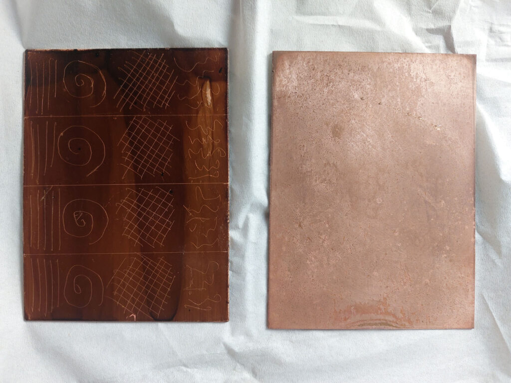
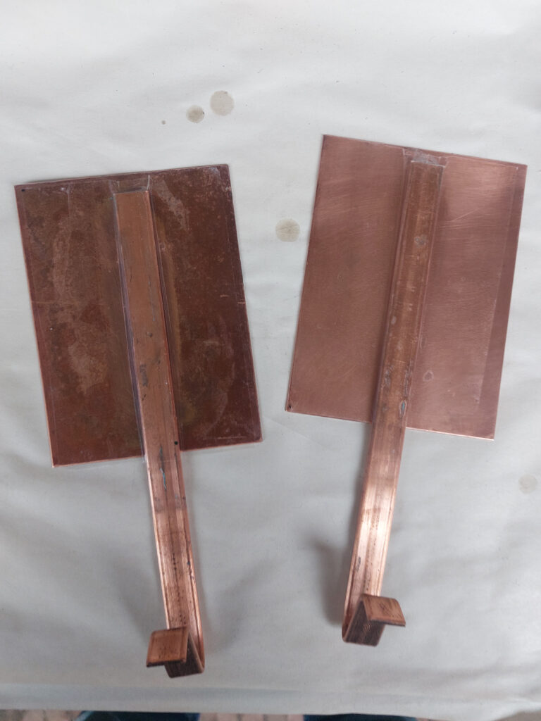
Both the etched plates were then cleaned of ground and de-greased ready to ink up for printing. The two plates are shown below.
<insert here image of both plates side by side>
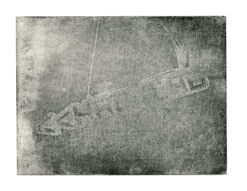
The prints are shown below.
Larger Plate
Using these determinations of etching times I prepared a larger plate (15x20cm) with a Charbonnel liquid ground.
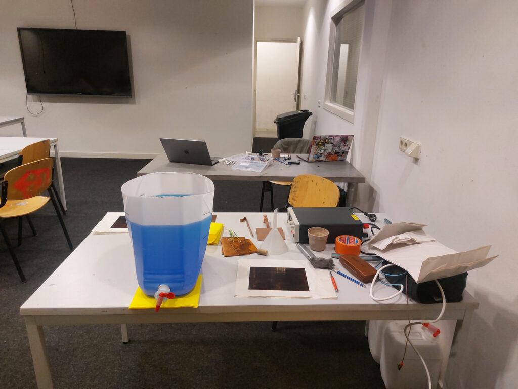
I set up the electro-intaglio tank in the classroom and etched for 30 minutes at 5V.

Then, I cleaned off the ground using VCA, degreased the plate with soy and whiting as usual before printing the plate on Hahnemühle “Copper Plate” paper.
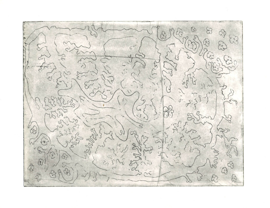
Photo Transfer using Oil-Based Ground
As a final step, I tried a photo transfer using Andrew Baldwin’s oil-based ground, called BIG. You take a laserjet monochrome print or a photocopy os an image and then using BIG and gum arabic you transfer the image as ground onto the plate. (For full details see Baldwin, 2016.)
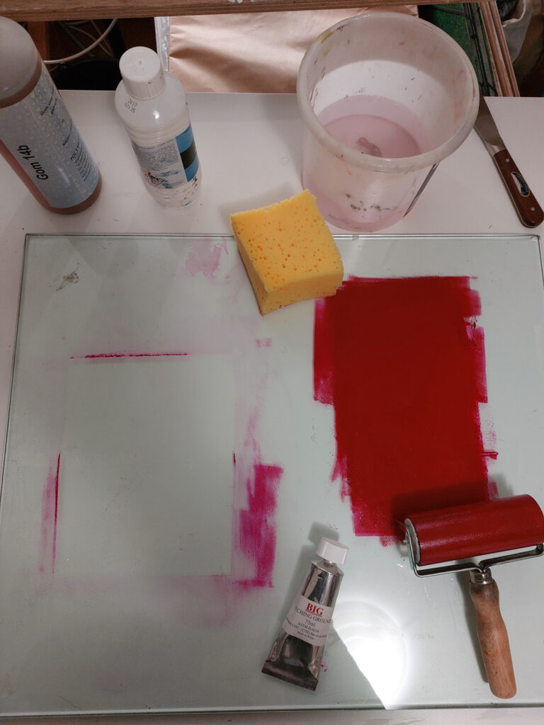
I prepared a plate of 15x20cm. In order to obtain any contrast I applied a rosin aquatint after the ground had been applied. The ground stood up very well to the heating to melt the rosin, no blistering or burning off occurred. I then etched this at 5V for 45 minutes.
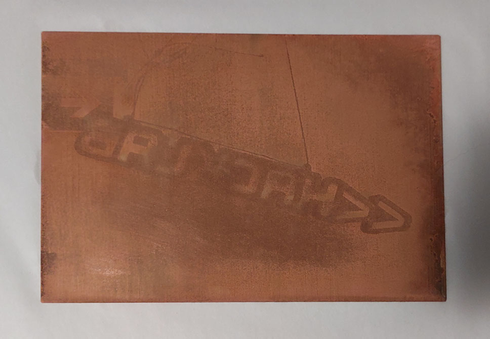
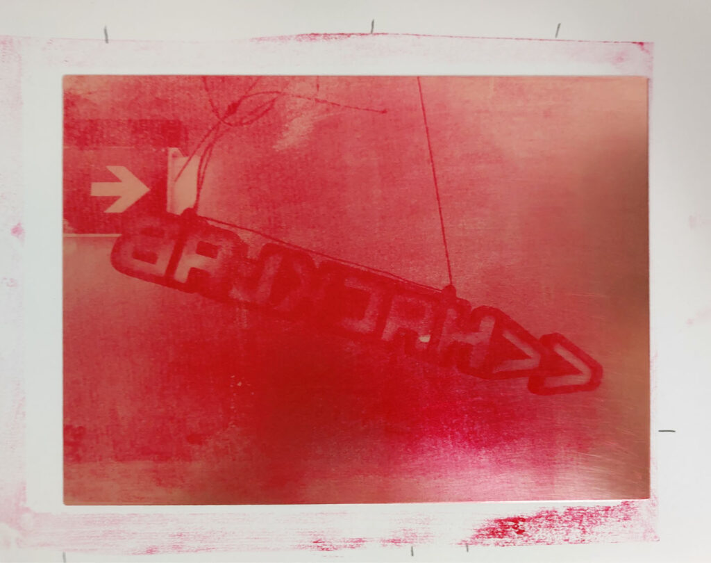
The print wasn’t great. The original image didn’t have enough contrast so that carried across into the ground transfer.
Bibliography
Green, Cedric. 2013. “Green Prints.” https://www.greenart.info/galvetch/contfram.htm
Andrew Baldwin. 2016. “Photo etching using BIG.” https://youtu.be/xK_K6LzyEqA?si=seYkefEczDiIgo0g